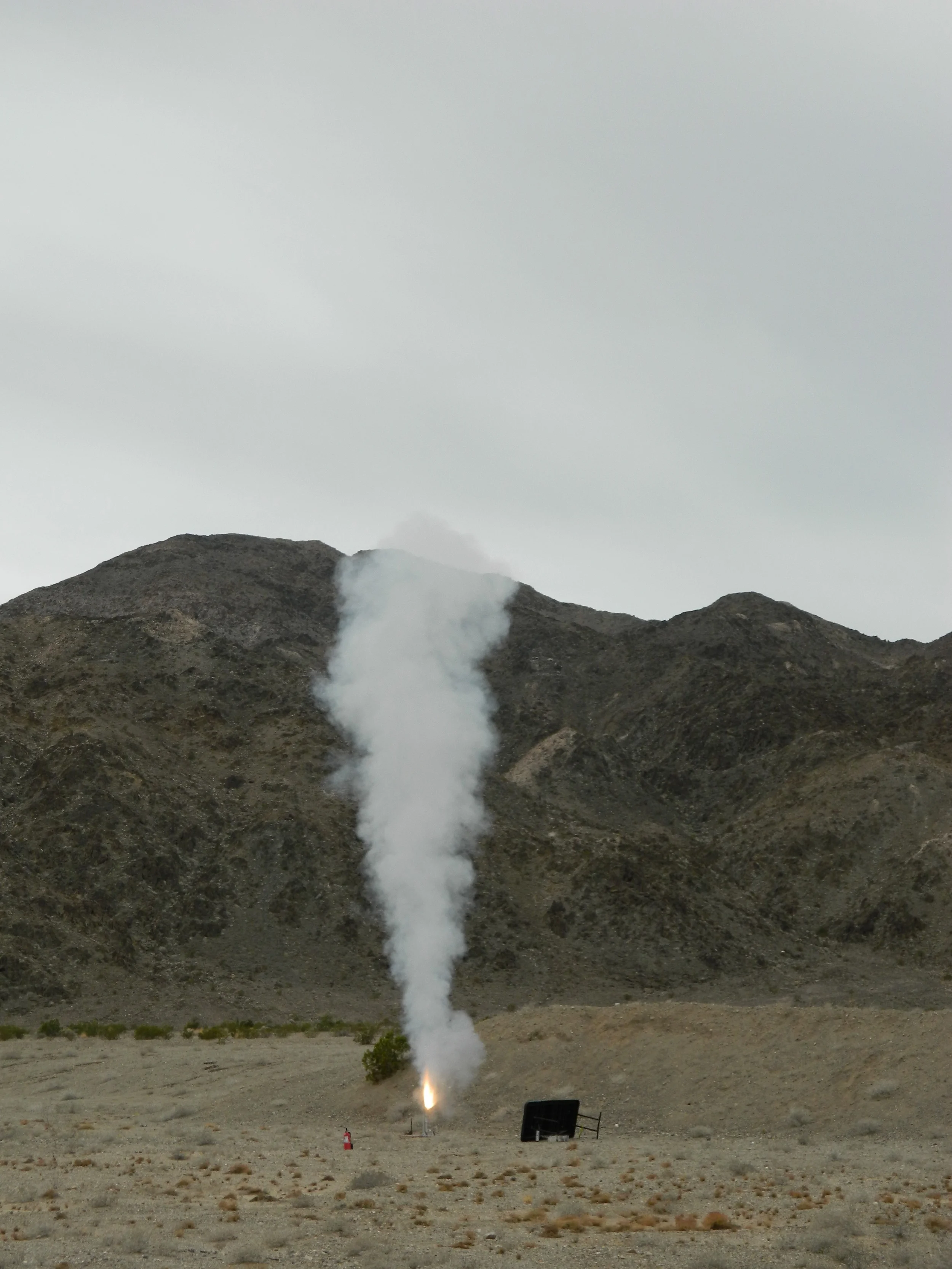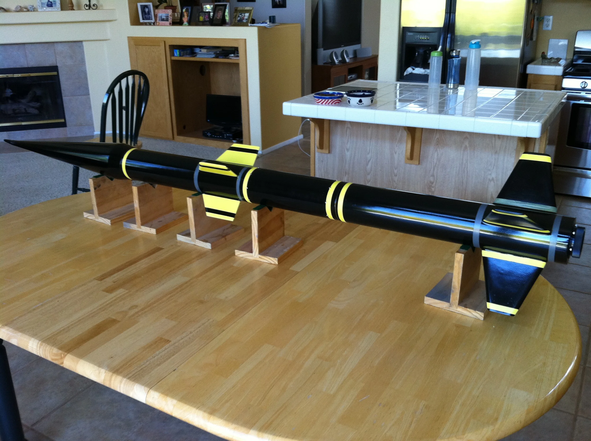
A multistage rocket I made to experiment with on-board camera lofting. The video from the onboard camera can be viewed here.
The sustainer is ignited via timer, which is triggered by a trip wire which breaks upon liftoff of the booster. For the sustainer igniter to receive current, a significant acceleration must also be detected, increasing the safety of the system.
The sustainer is lit by two electric matches which are augmented with pyrodex pellets. The igniter is secured to the forward end of the fuel grain with a small amount of epoxy, which prevents the igniters from being yanked out of the motor by the acceleration during liftoff.
All of the ignition electronics are stored on board the sustainer, since the booster naturally drag separates from the sustainer immediately after burnout. This is because the drag force is greater on the booster than on the sustainer, causing this separate body to decelerate faster than the sustainer. This is beneficial because it prevents the booster from being damaged by the flume of the sustainer upon ignition.


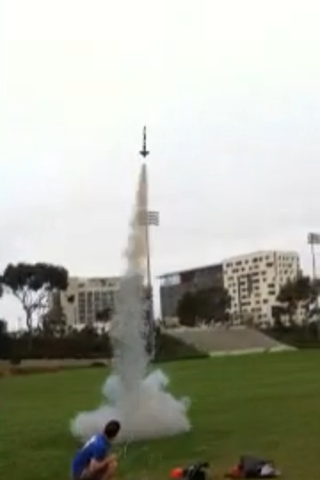
I'm not sure if rocket launching is actually allowed on Rimac Field, but who's up at 7 am anyway?
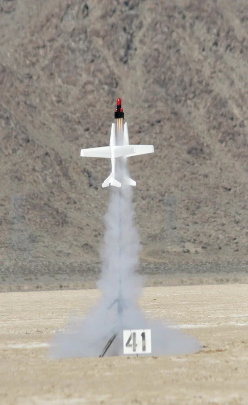
Balancing Forces
This unconventional design tows two gliders using low impulse, black powder rocket motors. The gliders are positioned opposite to eachother, canceling the lift force created by the air flow.
The design failed around two seconds into the flight when the foam joints of the glider failed due to the high stress of the wingtips in the airflow. Apparently the failure point for styrofoam is around 80 mph.

Bowling Ball Lofting
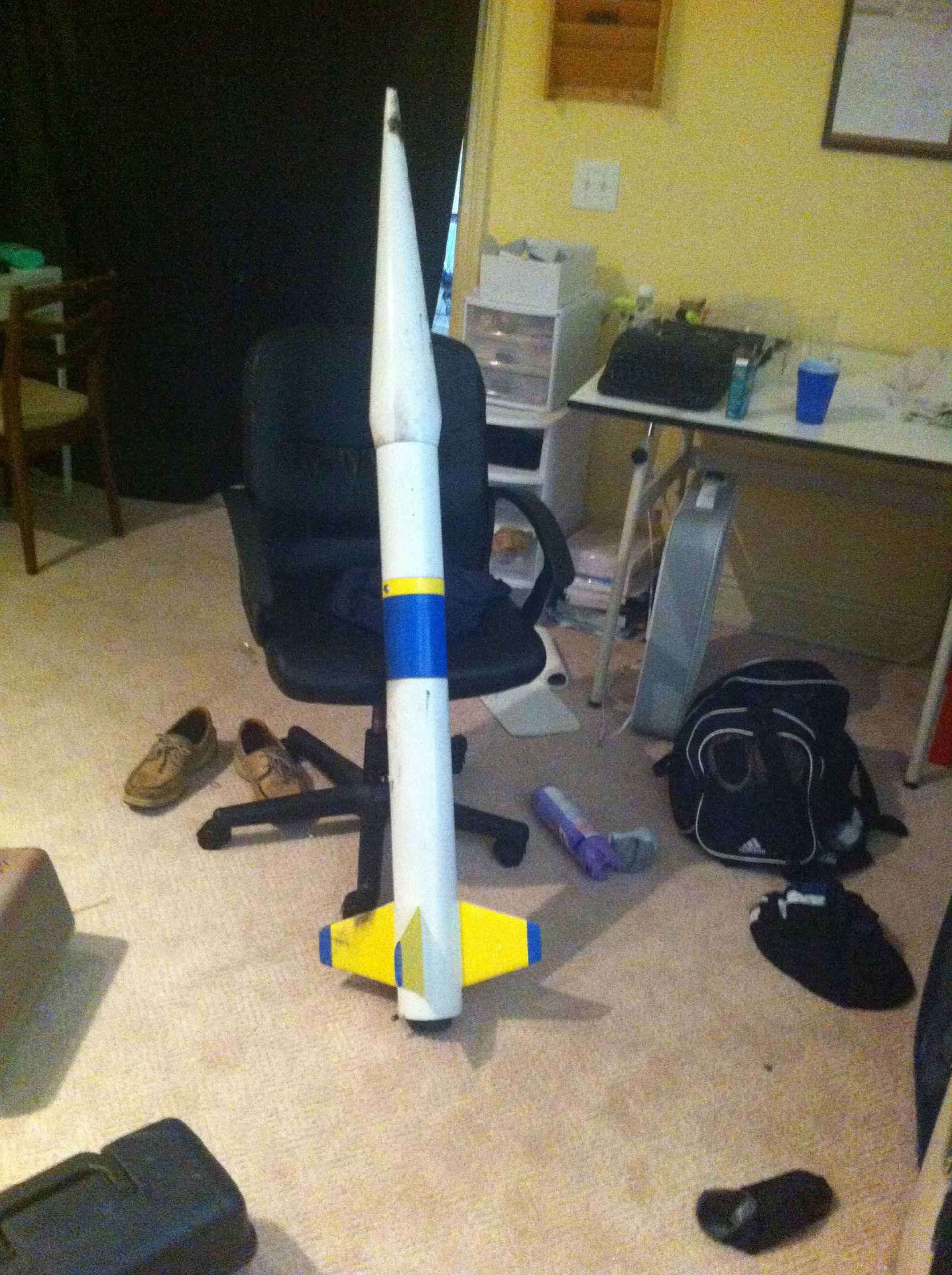
This design featured a fiberglass shroud to aerodynamically accommodate a bowling ball, which was placed as far forward as possible to increase stability. The shroud is hollow, allowing an 18 foot diameter parachute to be carefully compressed and stored inside.
The three fin design minimizes drag, and the span of the fins - which is equal to the diameter of the bowling ball - allows for the entire rocket to glide through the launch tube (see next photo) without becoming jammed.
Rocket Cannon
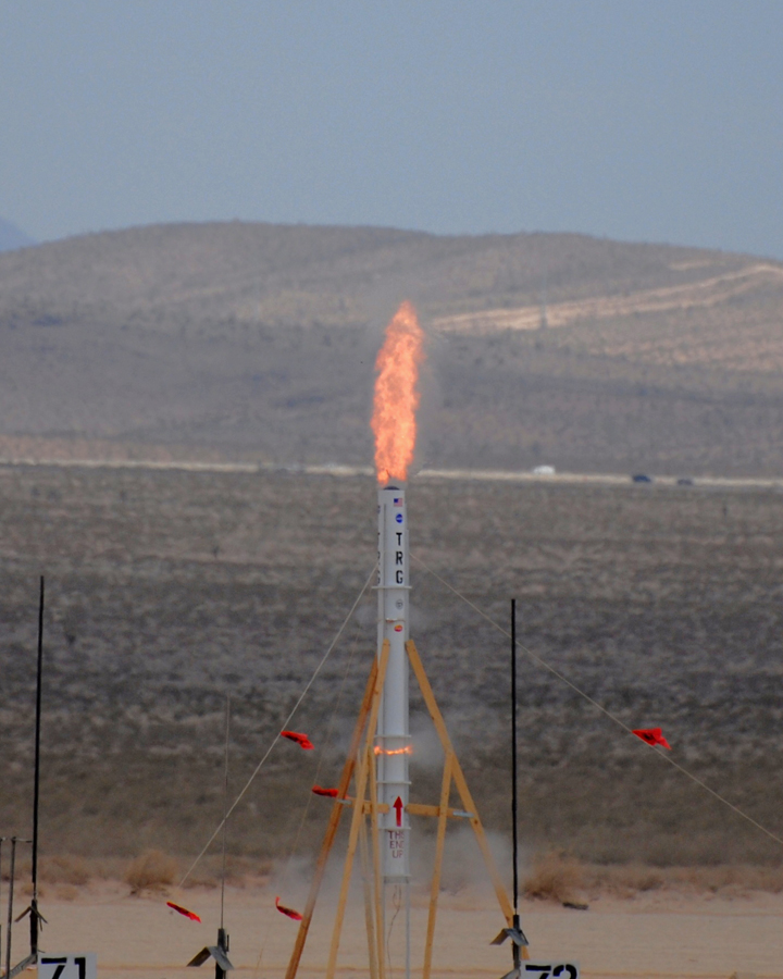
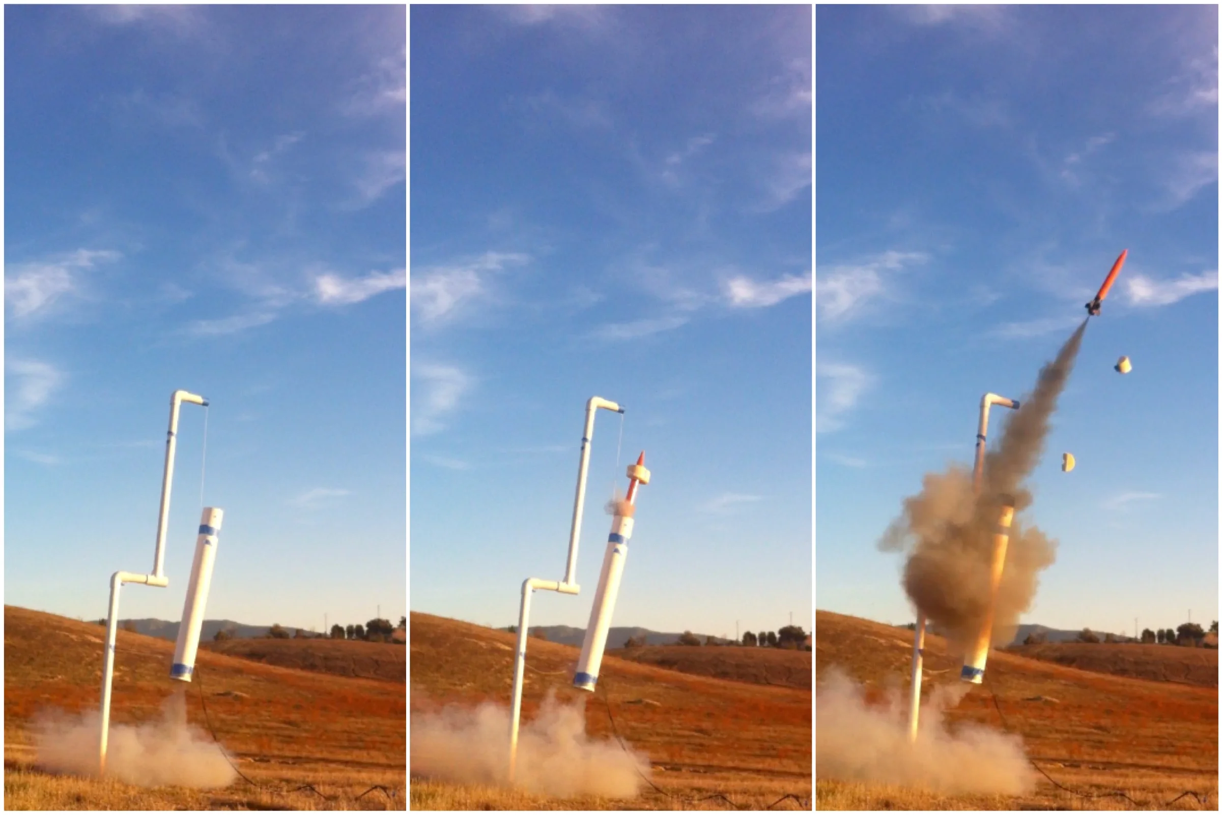
The bowling ball rocket (shown previously) received extra energy from a launch tube which was sealed at one end. The launch tube was made with aluminum railing and sono tubes and stood just over 17 feet tall. The "TRG" on the side of the tube stands for Temecula Rocket Group, a rocket club I founded at 15. TRG did numerous projects that were headed by high school students.
The pressure generated from the rocket ignition was so great that it blasted through the tape separating the bottom third of the launch tube from the middle third. The full rocket is not visible in this launch photo, but you can see the brim of the bowling ball exiting the end of the tube.
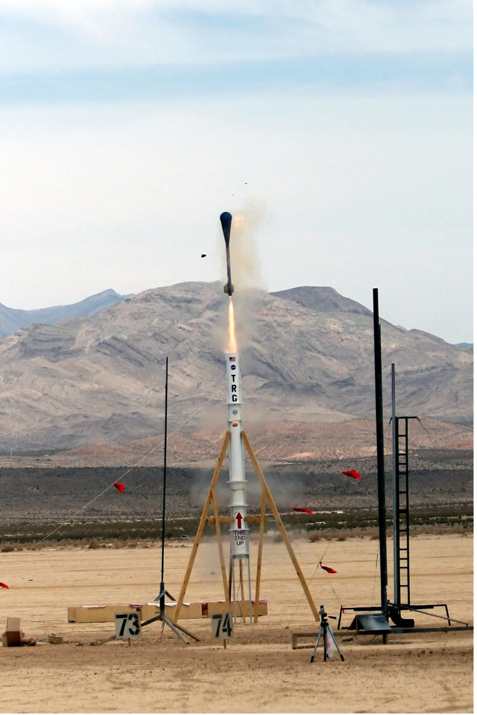
This second launch shows the entire rocket exiting the launch tube.

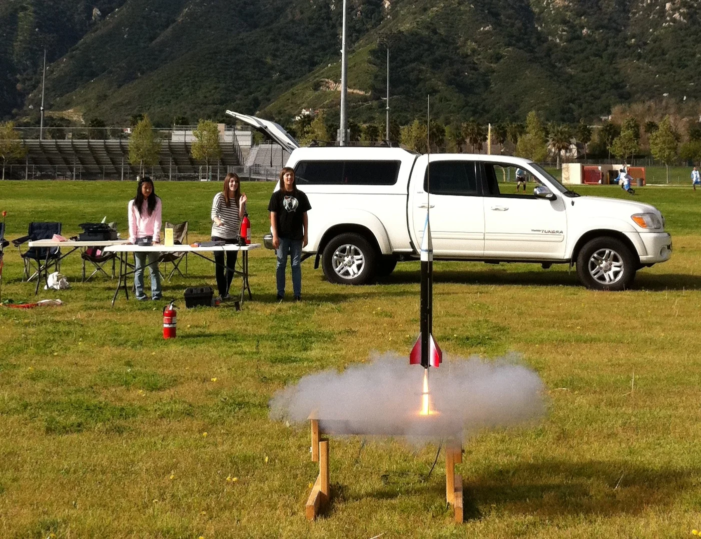
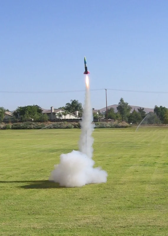
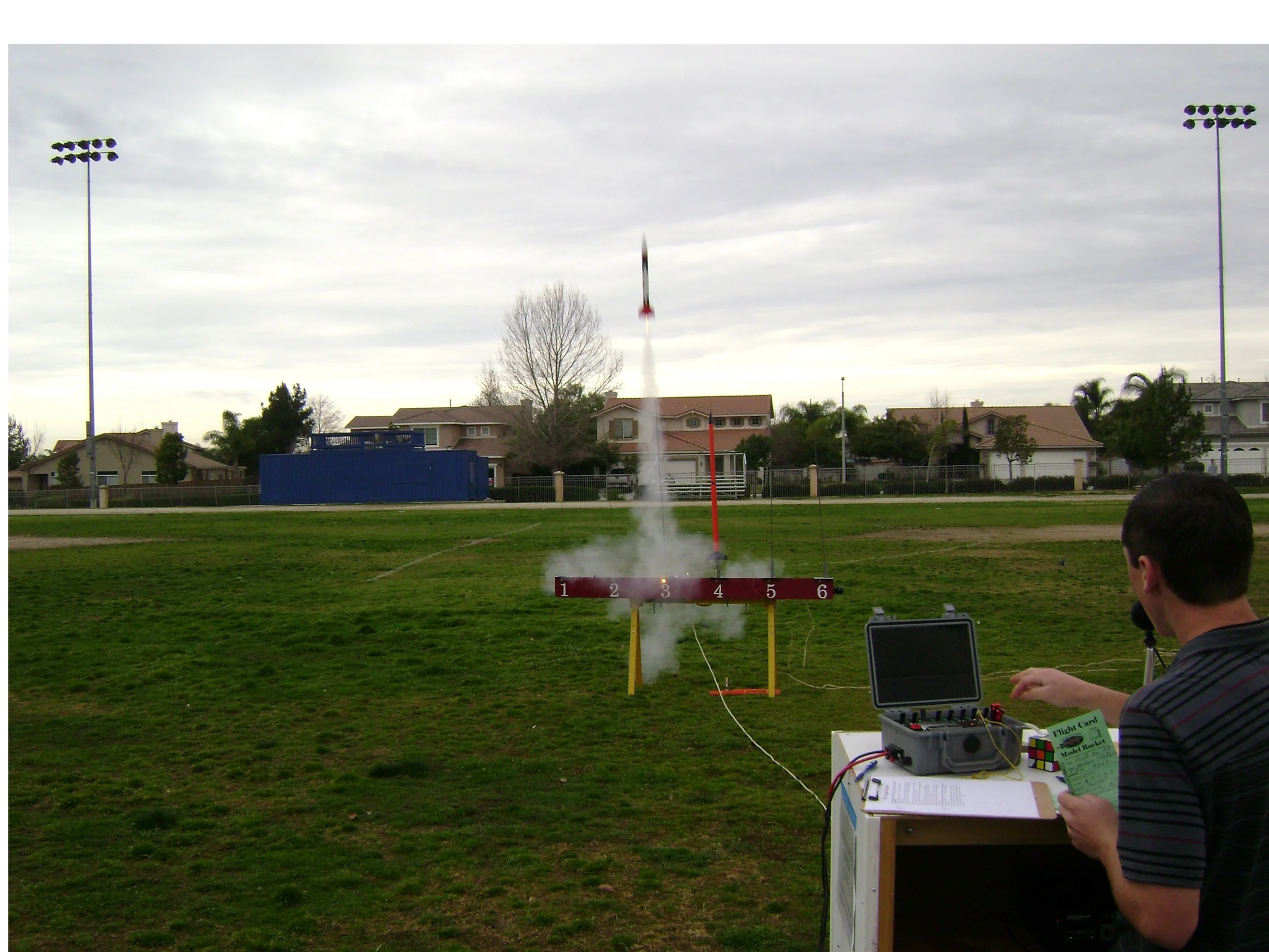
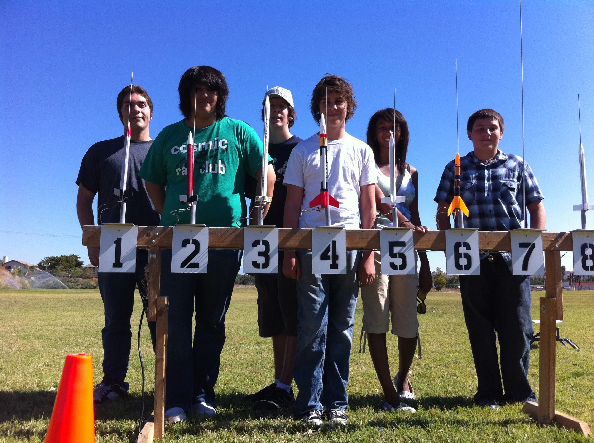
Temecula Rocket Group, a non-profit org I co-founded in middle school with several friends, provided kids in southern california with a venue to learn the basics of rocketry.

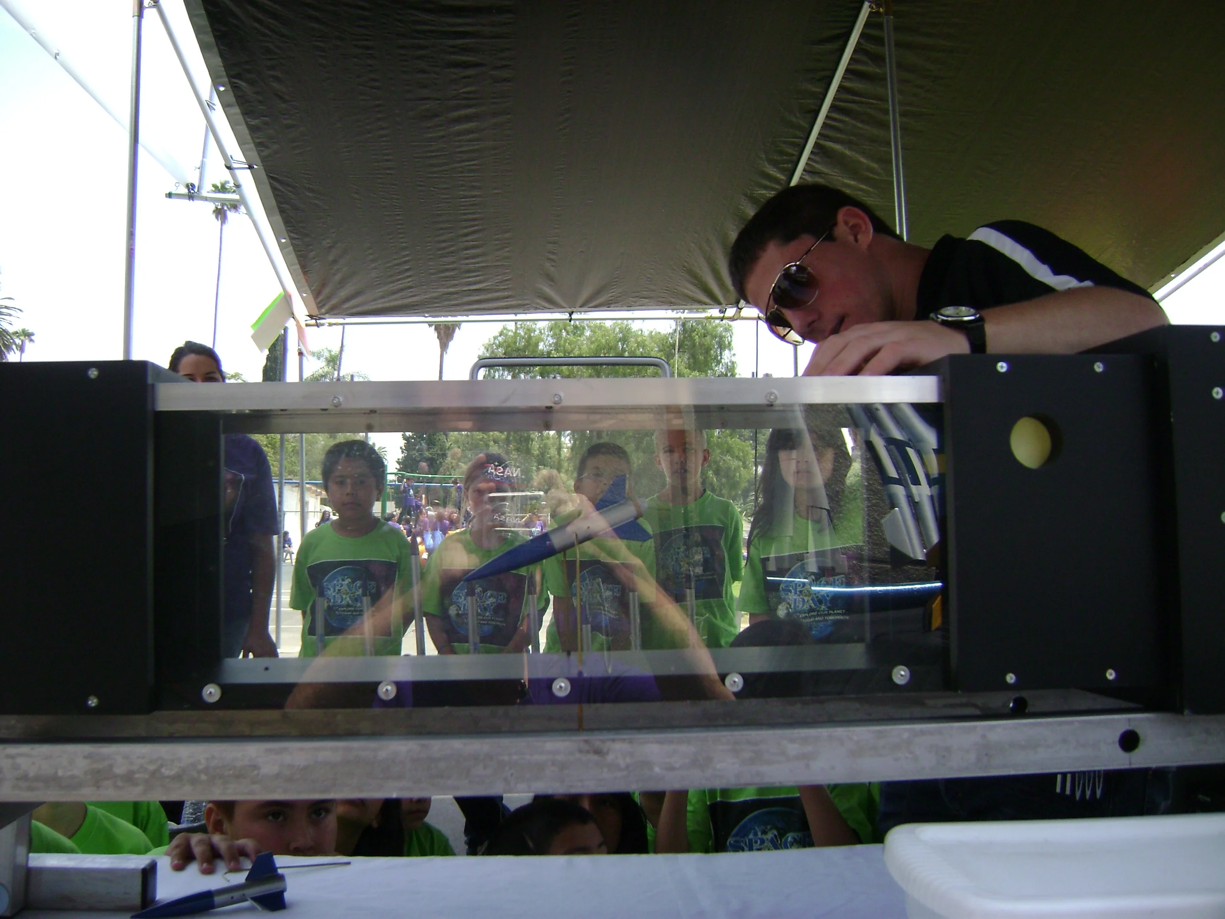
A wind tunnel powered by two industrial fans shows the basics of rocket stability to a crowd of elementary school students at Lockeed Martin's Space Day.

The front yard isn't off limits for testing.

Guidance
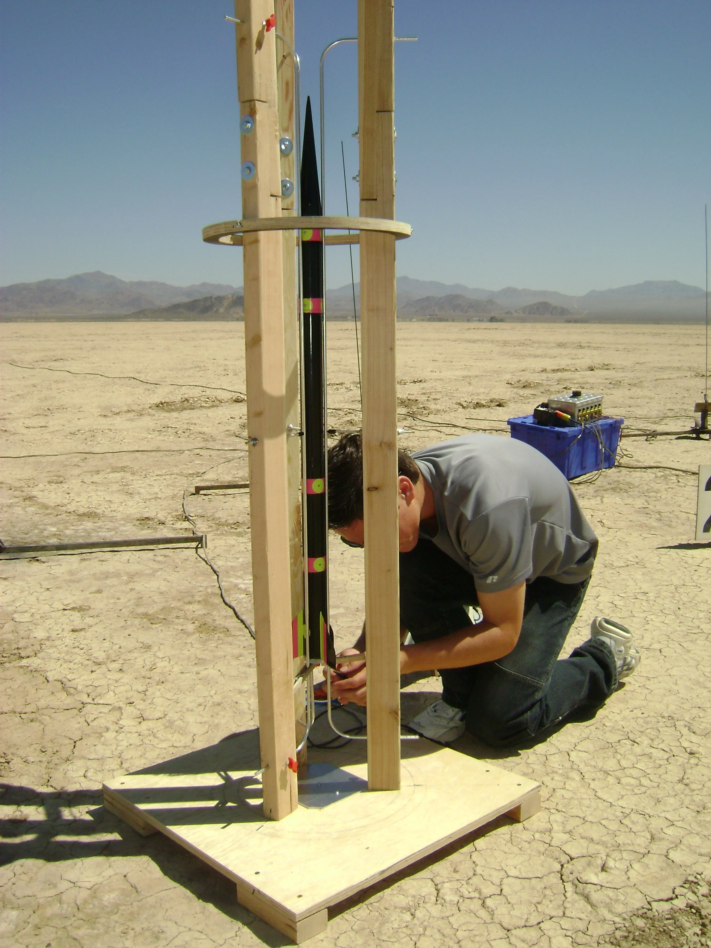
Unlike larger, gimbaled rockets, smaller solid fuel rockets are aerodynamically stabilized. This means that during the initial acceleration some sort of structure is required to keep the rocket on a vertical flight path until enough air is passing over the rocket's control surfaces for it to achieve stable flight.
Many launch pads use a rail or rod system with an exterior attachment or launch lug, but for smaller, optimized rockets the parasitic drag caused by these exterior protrusions can become significant, so an aligned rail launcher, such as the one shown in this photo, can be beneficial.
A 4" nike smoke downscale after launch in the desert south of UCSD.

The electronics bay for the previous rocket.

A giant expanding-foam ball was the basis for a strange aerodynamic rocket experiment. See the next two photos.


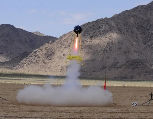
By having the relatively large mass of the rocket motor ahead of the guiding fins, even bizarre rocket configurations can fly stabily.



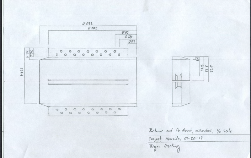

Drafting
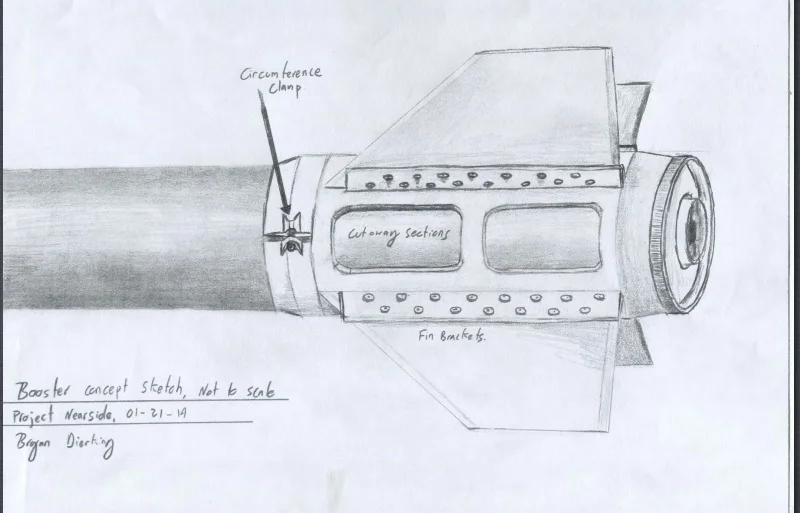
An early design of mine that featured a fiberglass boat tail with through the wall fin attachment.
While I now design mostly with CAD, I've always seen hand drafting as an important skill. I was fortunate to have several art teachers early in my education who stressed the fundamentals of drawing and sketching.
The next few photos show the actual construction photos of the rocket pictured, which was made for an altitude competition featured on a Science Channel special.

For supersonic rocket designs, I use high strength epoxy-impregnated fiberglass fin material. Traditional fiberglassing or carbon fiber can strip off a rocket if the joints aren't placed properly, but using material like the G10 shown provides a much greater core tensile strength than plywood.

Adhesion occurs on both a chemical and physical level. Adhering fins to the airframe of a rocket can provide a smoother finish without the parasitic drag that can result from riveting, but requires special attention to ensure that full adhesion strength is created. By increasing the surface area on the root edge of the fins with small cuts into the material, the strength of the bond is increased.
The same concept occurs on a smaller scale when course grit sandpaper is used before adhesive is applied.

Small strips of balsa are used to easily align the fin while gluing. This is necessary as the fins are installed in while the fiberglass boat tail surrounds the motor tube.
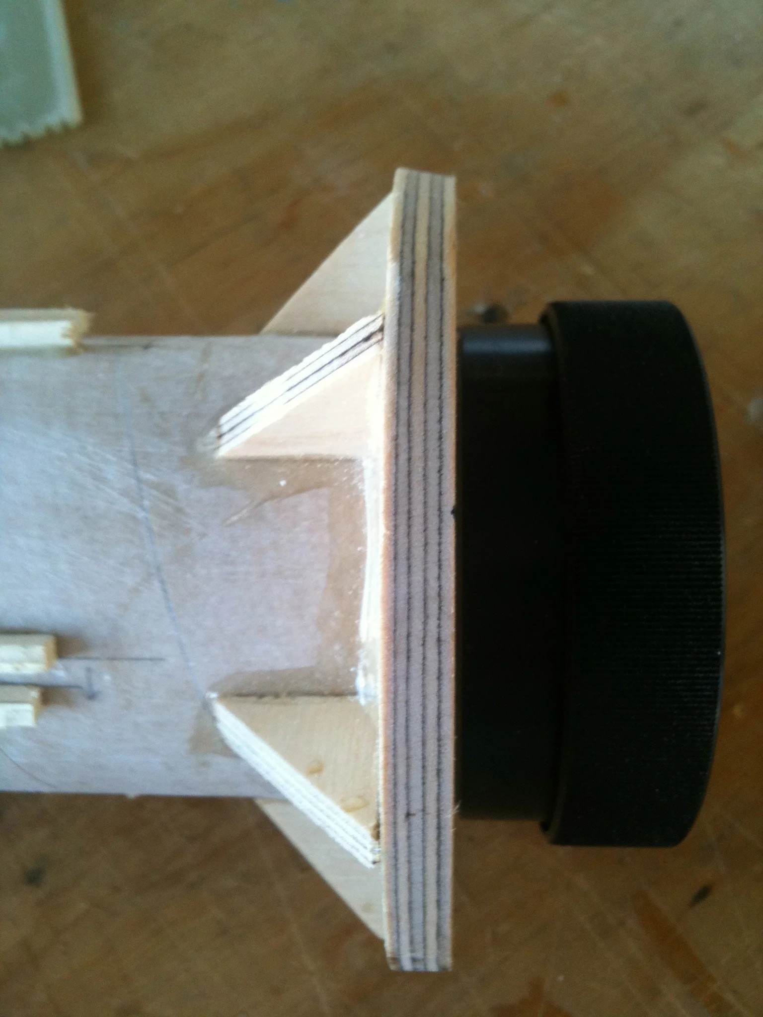
Small plywood wedges brace the area where the thrust from the rocket motor is applied.
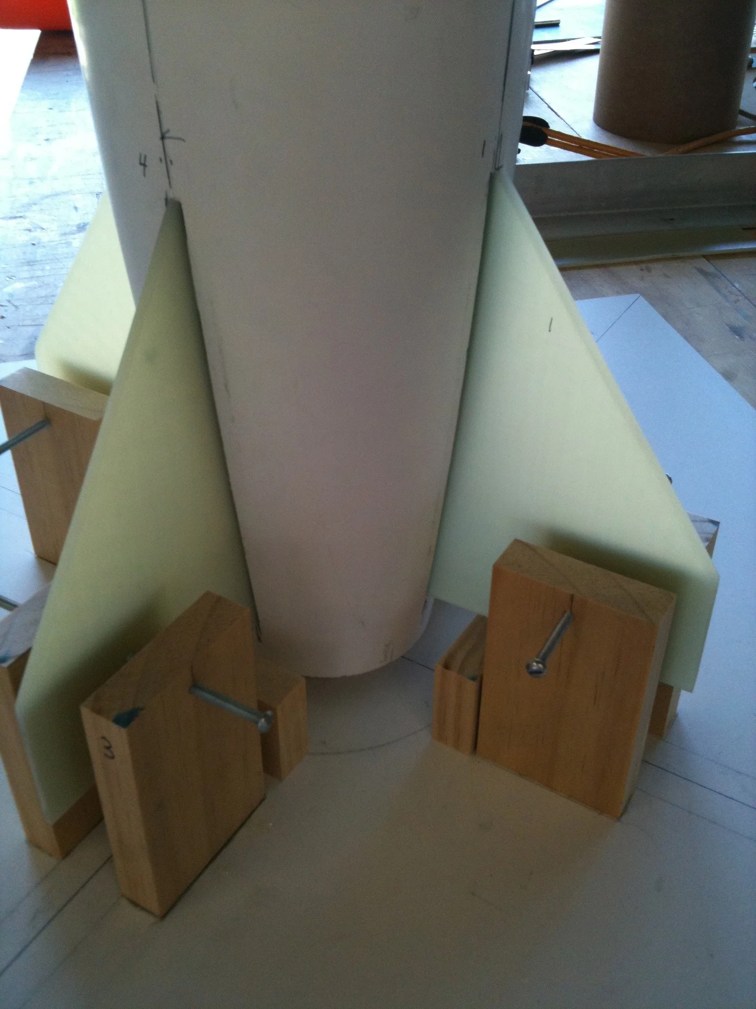
A fin positioning rig is used to ensure that the fins are perpendicular to each other. Small adjustments in the bolts that clamp onto the fins are made to ensure alignment.

The unpainted rocket before a final layer of fiberglass.

The fiberglass is carefully cut from templates that are made to allow some overlap for strength, but not so much overlap that weight is sacrificed.

The phenolic body tube of the rocket is visible through the wet fiberglass. The scratches are beneath the fiberglass cloth and were made with gritty sandpaper to increase adheasion.
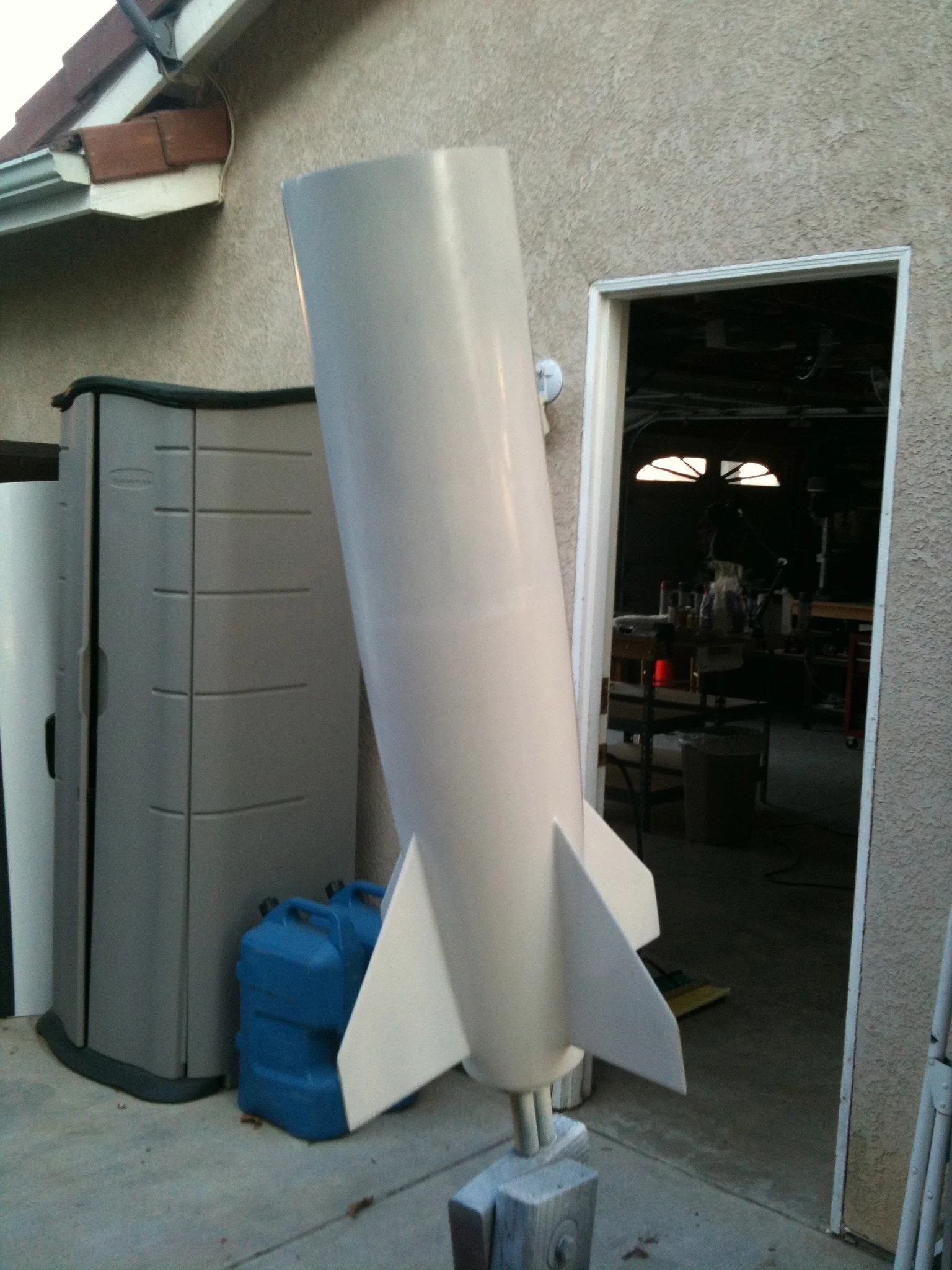
A primer coat of paint is added.

The finished rocket is loaded onto a rail launch pad.
